RESEARCH
&
DEVELOPMENT
![]()
The
GEMINI is undergoing extensive R & D and performance testing to
establish exactly how much more power has been obtained from placing
magnets on both sides of the energized coil.
It is expected that
while the first prototypes will not operate to their maximum capacity,
with the refinements and fine tuning that are resulting from our current
R
& D the GEMINI will soon considerably out perform conventional
electric motors. Large gains are being made through finer manufacturing
tolerances and improvements to the commutation system.
There has been some confusion regarding the out put of the Gemini Electric Motor & Generator. While it is undoubtably a superior design which will become the new standard for all electric motors and generators, it is NOT PERPETUAL MOTION or OVER UNITY. It has a unique characteristic which is, the permanent magnets either side of the energized coils act as a choker and restrict the amount of electric current that can be drawn by the copper wire wound around the cores. This has the effect that if the Gemini Electric Motor is running under load, and producing good torque and r.p.m., but the load is increased to a point that the motor starts to slow down in r.p.m., the Gemini Electric Motor will reduce the amount of amps used to match the r.p.m., thus maintaining very high performance and efficiency. All other electric motors when under an increase load will draw more amp, and if the increased load causes the r.p.m. to slow down, it will draw even more amps, while reducing performance and efficiency.
Because
of the initial cost of the two radius's curved permanent magnets back in
2000, ( we had to pay for the actual magnet dies to be made ) we have used
a 210 mm outside diameter as the normal size and have varied the width to
suit performances required. We are currently making a 500 mm outside
diameter Gemini Electric Motor and Generator, and fortunately did not have
to pay for the new magnet dies, which was a considerable cost saving. We
have made six pole and twelve pole Gemini Electric Motors and Generators.
I should point out that the only difference between a Gemini Electric
Motor and a Gemini Electric Generator is the Gemini Electric Motor has
three hall effect sensors and a electronic controller, while the Gemini
Electric Generator uses two bridge rectifiers to change the AC current to
a DC current. A Star or Delta wiring configuration is used. If a carbon
brush commutator is used, it is less efficient but much lower in cost to
manufacture, and uses a different wiring configuration.

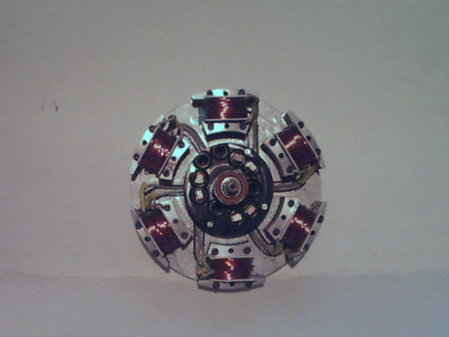
The photo above shows the six energized coil Gemini Electric Motor with a Twelve energized coil Gemini Electric Motor in the back ground. The six energized coil Gemini Electric Motor on the right has a carbon brush commutator.

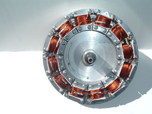
This is a clearer photo of the six energized coil Gemini Electric Motor & Generator.
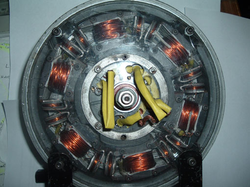
This is a six energize coil rotor with a carbon brush commutator fitted in the center.

The Picture above shows a six energized coil rotor and the wiring suitable for a carbon brush commutator.
The is picture shows a twelve energized coil rotor, the carbon brush commutator is fitted to the back of the rotor ( not shown ).

This twelve energized coil rotor is an attempt to see if it is possible to fit a motor and generator on the same rotor. Six of the Energized coils are wired as a motor, and the other six energized coils are wired as a generator. It works, but like all machines there are mechanical losses, and therefore you get out less electric current than is put in.

The drawing above is taken from the patent and shows the first practical application of what is known as Transformer Induction. As the "H" shaped energize coils change from North magnetic pole to South magnetic pole by the commutation of the motor, by putting pick up plates that have a energized coil between them, it generates an AC electric current, quite independent of the motor windings. It works, but again it reduces the motor performance by the amount of current produced. This was an attempt to use what were thought to be unused magnetic fluxes.

This is a photo of a Gemini Electric Motor & Generator using the transformed induction system of wiring. It works but is getting to complicated.
This is a photo of a Gemini Electric Motor & Generator using the transformed induction system of wiring. It works but is getting to complicated.

This is a six energized coil Gemini Electric Motor & Generator with two sets of windings on each coil. The idea was that one set of windings was a motor, and the other set of windings was for a generator. This unit used a carbon brush commutator. Again it worked, but due to mechanical losses it did not produce enough power that it could run its self or produce more than it consumed.
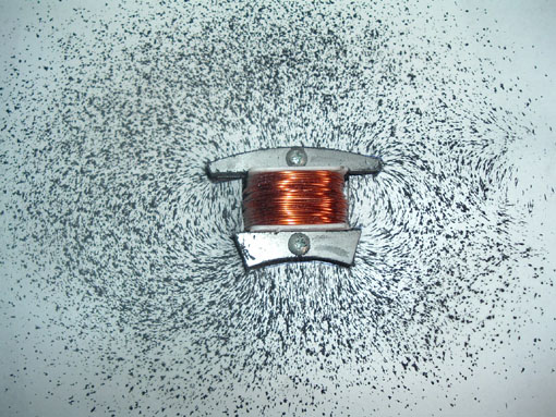
This shows the magnetic flux lines of an energized coil. The picture is obtained by spraying the paper backing with an adhesive spray, letting the energized coil into the back ground half way, and then sprinkling permanent magnet filings on to the background. The permanent magnet filings are obtained by grinding a Ceramic permanent magnet with a carborundum grinding wheel. Each grinding splinter is an independent permanent magnet. By using a spray glue on the back ground, the splinter stays in the position it lands on the background, it has been noticed that as many splinters land with out the glue, they change direction and give a false reading.

This is an energized coil, with a permanent magnet, through magnetized, which closes the magnetic flux circuit between the ends of the "H" shape energize core. This was tried in an attempt to increase the strength of the magnetic poles of the "H" shape core. Did it make any difference ? Inconclusive tests.

A normal "H" shape energized coil and a "H" shape energized coil fitted with two permanent magnets, closing the magnetic flux circuit between the ends of the "H" shape core.
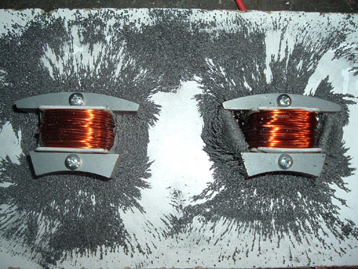
This is the same as above with both Energized coils energized. It shows the magnetic flux lines created. I should have used the spray glue mentioned above to get much clearer definition of the actual magnetic field lines.
These and other tests were made to see if the Gemini Electric Motor & Generator could be improved. The conclusion reached was it is better and much simpler to make a Gemini Electric Motor as a motor, and a Gemini Electric Generator as a generator instead of trying to make them in one unit. It should also be remembered that the Gemini Electric Motor immediately becomes a generator if the shaft is driven. As in regenerative braking, using the motor to slow the vehicle down, going down a hill ect. If the carbon brush commutator is used it is automatic, and if the electronic controller is used it needs the regeneration feature built into the electronic controller/